Old BMS General Thread

Threads relating to the BMS system begun by Peter Perkins

Moderators: GregsGarage, retepsnikrep

User avatar
timpootle
Posts: 1362
Joined: Wed Mar 14, 2007 12:13 pm
Location: Chorlton-cum-Hardy, UK

Re: Updated Schematics and PCB update.

Postby timpootle » Thu Jul 10, 2008 1:58 pm

retepsnikrep wrote:I've noticed it's a bit lonely in this thread :(

Keep talking Peter! I'm following this with interest while I wait for my 200Ah cells to arrive.
Tim Crumpton

User avatar
retepsnikrep
Posts: 1387
Joined: Sat May 26, 2007 4:50 pm
Location: North Yorkshire England
Contact:

Slave Pricing and Temp Sensing

Postby retepsnikrep » Thu Jul 10, 2008 2:55 pm

Picaxe 08M chips can be had at 1.00 each excl vat in bulk. Not too bad. Later can buy bare pic chips and program in assembler.

Testing them today seem happy to work down to about 1.8V, so should cover most scenarios. :wink:

I've also changed to an I2C device the DS18B20 for pack temp sensing instead of the LM35 which will allow a lot of individually addressed sensors on the same input, so people can put them where they want in the pack, on the controller, on the motor etc etc. It also has a wider temp range -55 to +125C :)
Regards Peter

Two MK1 Honda Insight's. One running 20ah A123 Lithium pack. One 8ah BetterBattery Nimh pack.
One HCH1 Civic Hybrid running 60ah A123 Lithium pack.

User avatar
qdos
Posts: 2089
Joined: Fri Apr 27, 2007 10:26 pm
Location: Dorset
Contact:

Re: Updated Schematics and PCB update.

Postby qdos » Fri Jul 11, 2008 7:27 am

retepsnikrep wrote:I've noticed it's a bit lonely in this thread :(


It may look it Peter but there's more of us out hear reading it with much interest. In fact I've been wondering if one or other of you authors of the thread might precee it for an article in Plugged In as it's excellent stuff and not everyone reads the forum

User avatar
retepsnikrep
Posts: 1387
Joined: Sat May 26, 2007 4:50 pm
Location: North Yorkshire England
Contact:

Write Up

Postby retepsnikrep » Fri Jul 11, 2008 11:40 am

I will do a write up when it's finished and working properly. I need every minute I've got before the cells arrive from China to work on the design/software.
I did do a comprehensive write up on my very old and agricultural relay :shock: driven BMS for my van 5 years ago.

http://www.solarvan.co.uk/solarvanbmsproj.zip

Pretty cringeworthy now, but I learnt a lot from that first one. :lol:

For now just some updated and tweaked files/schematics.

www.solarvan.co.uk/Master100708V170.txt
www.solarvan.co.uk/Master110708.jpg

www.solarvan.co.uk/Slave100708.txt
www.solarvan.co.uk/Slave110708.jpg
Regards Peter

Two MK1 Honda Insight's. One running 20ah A123 Lithium pack. One 8ah BetterBattery Nimh pack.
One HCH1 Civic Hybrid running 60ah A123 Lithium pack.

User avatar
ChrisB
Posts: 4657
Joined: Fri Jul 14, 2006 11:33 am
Location: Hampshire on the Southcoast
Contact:

Re: Updated Schematics and PCB update.

Postby ChrisB » Fri Jul 11, 2008 6:11 pm

retepsnikrep wrote:I've noticed it's a bit lonely in this thread :(


I'm ear wiggin on the side :wink:

ChrisB
I reject reality and substitute my own !!!!!!

User avatar
dillond666
Posts: 139
Joined: Mon May 26, 2008 7:52 pm
Location: Central Scotland

28x?

Postby dillond666 » Fri Jul 11, 2008 8:37 pm

Holy smoke, this project has really grown legs!............the 18x has grown into a 28x :lol: I guess the picaxes are so low priced it is as well to have a degree of future proofing in the hardware.
I was wondering if a 2W load resistor is meaty enough, I like bobc's idea of using a logic level FET for switching on the load, a 30A version is only 28p from rapid electronics, so the option is there to use a larger external load if necessary. I suppose it depends on the charger cutback arrangement. Do you still use the zivan? If so, is it possible to interface it with the master board?

I used to be a happy, relatively normal bloke before this thread started! Now I'm sneaking away to caress and fondle the pages of the Picaxe book....ooh the shame of it
:oops:

User avatar
retepsnikrep
Posts: 1387
Joined: Sat May 26, 2007 4:50 pm
Location: North Yorkshire England
Contact:

Re: 28x?

Postby retepsnikrep » Sat Jul 12, 2008 5:28 am

dillond666 wrote:Holy smoke, this project has really grown legs!............the 18x has grown into a 28x :lol: I guess the picaxes are so low priced it is as well to have a degree of future proofing in the hardware.
I was wondering if a 2W load resistor is meaty enough, I like bobc's idea of using a logic level FET for switching on the load, a 30A version is only 28p from rapid electronics, so the option is there to use a larger external load if necessary. I suppose it depends on the charger cutback arrangement. Do you still use the zivan? If so, is it possible to interface it with the master board?

I used to be a happy, relatively normal bloke before this thread started! Now I'm sneaking away to caress and fondle the pages of the Picaxe book....ooh the shame of it
:oops:


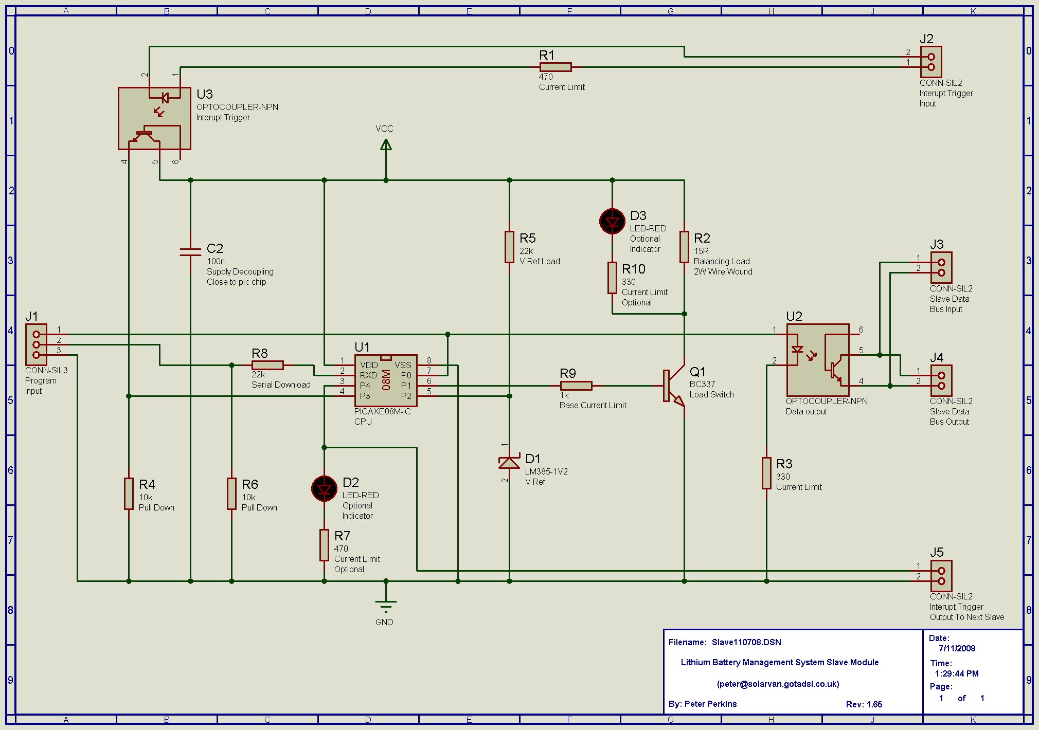
Yes changing to the 28X1 did add a few more inputs, but I did it mainly because it has a timeout function on the slave data serial input, so the Master software does not become stuck waiting for a slave to respond if there is a hardware failure on a particular cell. It can now detect that condition and report appropriately. Vital to the whole system. :wink:

I choose the 2w 15R balancing load as that has been proven to work over the last four years on Cedric's cell controllers. The balancing load of about 250ma was suffcient to keep 200AH cells in balance during that time so I'm happy with that. On smaller cells it will be even more effective. 8)

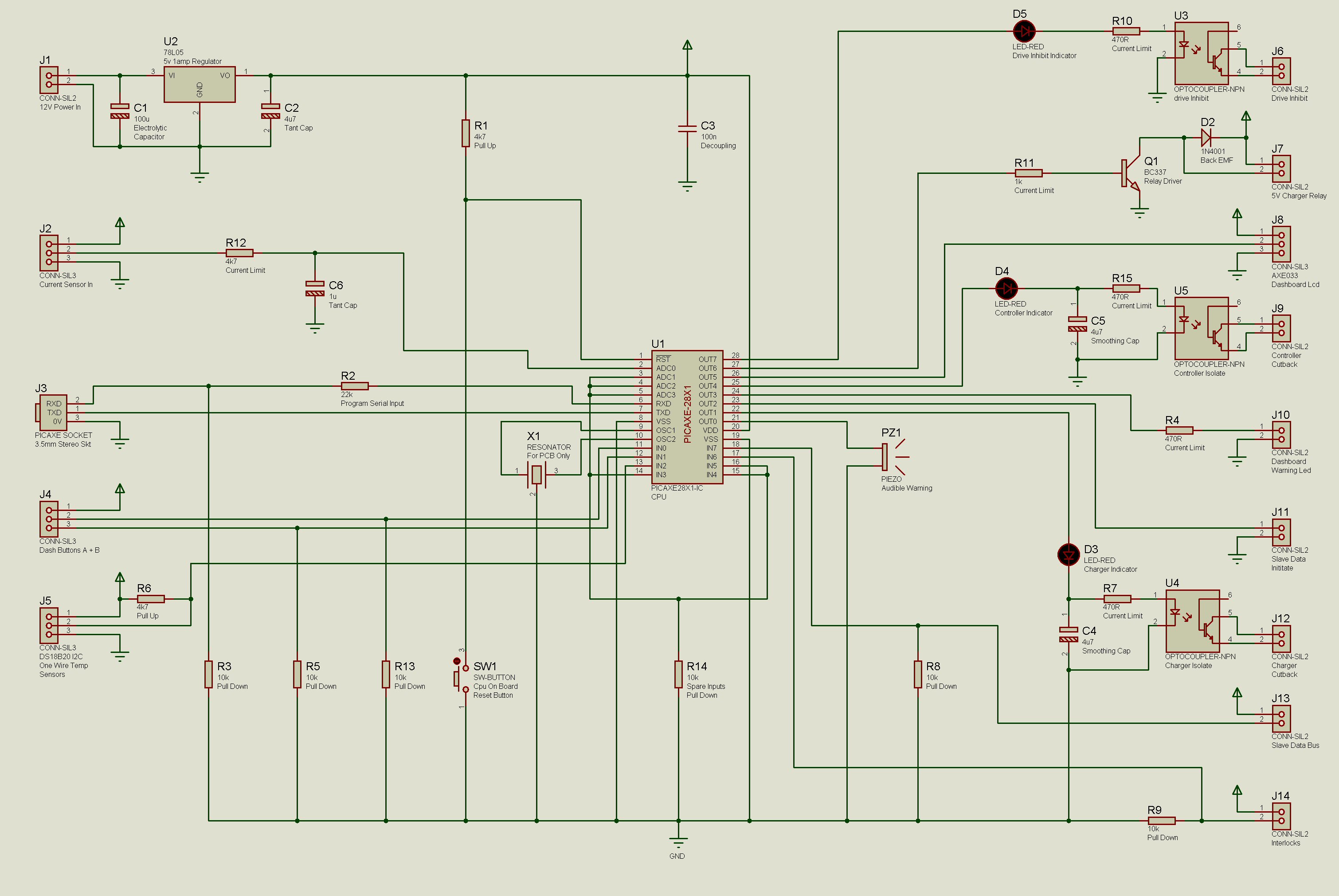
I will be using a Zivan NG3 and the same Charger cutback arrangement. The Picaxes don't do DAC output in the conventional sense ASFAIK, you have to use a PWM output but this drives an opto through an RC smoothing circuit so in effect the opto led changes brightness smoothly in response to changes in PWM Mark/Space ratio. I haven't decided wether to pull charger voltage up or down with opto control yet. Pulling it up gives a slightly more fail safe arrangement I think. :? The Master schematic incorporates this PWM control function for both Charger and Controller cutback :D

Many, many years ago as a callow youth I used to sneak about with a copy of Mayfair :oops: :wink: Now I skulk about, collar turned up, in an old fleece, with a carrier bag full of Schematics, Software printouts, Pic data sheets and the like :shock: :lol: How times have changed!

I've just ordered the 08M Picaxes to start building up the 50 slaves I need when the pcb's are finished. I have also ordered a PIC assembler level programmer so I can look at converting the Slave software to assembly and program it direct into bare pics once it's all tested. This will make the slaves a bit cheaper but owners won't be able to re-program themselves like they can with the Picaxe versions.

One of the Picaxes main attractions is the ease of re-programming 8) with a simple serial/usb cable and the free software it means as We/I release upgraded Slave/Master software people can just download it to there system in a few minutes. The free 32mb Picaxe basic editor is below, download it and tinker around!

http://www.rev-ed.co.uk/software/bas805.exe

The current sensor I will be utilising is based on the Allegro ACS754LCB series, which gives an 0-5v Output covering -100 to + 100A range.

5v output = +100A
2.5V output = 0A
0v output = -100A

Resolution will be about 200ma with the Pic 28X1 10bit adc

This will be mounted off the master board to reduce interference.

http://www.farnell.com/datasheets/75747.pdf

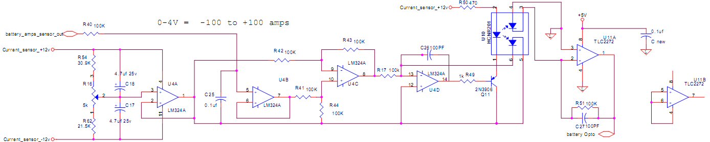
Other sensors can be used but conditioning of the signal will be reqd to ensure signal is within 0-5v for the Pic ADC input.

If you were using a current sensor with a positive/negative voltage output (quite common) then this example circuit will condition signal, opto isolate it and bring it to 0-4vdc output with a centre (2.0v) 0 amp position.

www.solarvan.co.uk/CurrentSensorCircuit.jpg

I will be building my battery pack up into 10 cell subpacks for testing which will only be connected together for final install/bench test.

I can thoroughly bench test each 10 cell subpack before install and it's a lot safer at <40V per block, the entire pack charged voltage will be nearer 190V :shock: a bit too dangerous for tinkering with for my liking. Still got to be careful though I don't want any expensive smoke or singed dignity.

Back to work now!!
Regards Peter

Two MK1 Honda Insight's. One running 20ah A123 Lithium pack. One 8ah BetterBattery Nimh pack.
One HCH1 Civic Hybrid running 60ah A123 Lithium pack.

User avatar
retepsnikrep
Posts: 1387
Joined: Sat May 26, 2007 4:50 pm
Location: North Yorkshire England
Contact:

Improving Slave Data Transmission Speed

Postby retepsnikrep » Sat Jul 12, 2008 11:31 pm

I have been thinking about transmission speed over the common 2400baud serial data bus.

At the moment I am transmitting a 16bit word variable containing the Cell Voltage (200-400 or 2.00-4.00V). 50 Cells takes an estimated second approx for all the data to be sent, but I want to improve on that.

This really is a waste of most of a byte and time consuming to transmit, so I have now crammed the result into a single byte without sacrificing accuracy. 8)

Basically the only V range we are interested in is the normal pic/lithium cell operating range, which is about 1.75-4.30V, anything outside that is indicative of a serious problem anyway.

The additional Slave code simply tests the cell voltage to see if it is >430 (4.30V) or < 175 (1.75V), if it is, it sets the transmitted byte to 0 which indicates to the Master "Houston we have a problem!".

If it's within the normal range it subtracts 175 (1.75) from the result which gives a value that can fit into a single byte with 10mv resolution.

This byte is then transmitted and the Master simply adds 175 back to it to get the correct Cell voltage in the 16bit word variable at the other end :)

Means 50% less data to send :shock: Should be twice as fast :wink:

Updated Slave Code

www.solarvan.co.uk/Slave130708.txt
Regards Peter

Two MK1 Honda Insight's. One running 20ah A123 Lithium pack. One 8ah BetterBattery Nimh pack.
One HCH1 Civic Hybrid running 60ah A123 Lithium pack.

User avatar
retepsnikrep
Posts: 1387
Joined: Sat May 26, 2007 4:50 pm
Location: North Yorkshire England
Contact:

Busy Bee

Postby retepsnikrep » Sun Jul 13, 2008 8:47 am

As a follow up to my last post I am now using a 128 byte Ram Scratch pad in the Master software to save all the single byte Cell Voltage data to during the faster Serial transmission.

Once the data has been transferred from the pack Slaves to the Master I can then manipulate/display this data as reqd.

Much better IMO but limits Max number of cells to 128, as that's all the scratchpad ram available in the 28X1 Picaxe Pic.

Should be more than enough for most systems.

www.solarvan.co.uk/Master130708.txt

I'm working on a subroutine to allow a horizontal scrolling display on the Lcd of all the cell voltages when a button is pressed.
Regards Peter

Two MK1 Honda Insight's. One running 20ah A123 Lithium pack. One 8ah BetterBattery Nimh pack.
One HCH1 Civic Hybrid running 60ah A123 Lithium pack.

User avatar
retepsnikrep
Posts: 1387
Joined: Sat May 26, 2007 4:50 pm
Location: North Yorkshire England
Contact:

Final Schematic checking

Postby retepsnikrep » Sun Jul 13, 2008 10:33 am

It's so easy to make a mistake, as I did on this version of the Master schematic :oops:

www.solarvan.co.uk/Master110708.jpg

Can you spot it? It's something that operates with the Slaves?

I've corrected it below, but this highlights a serious problem, me checking my own stuff. :shock: You miss things. Can others have a good look at both schematics and flag up any obvious errors for me please. I'm very close to final pcb layout, and if I had used the above version it would not have worked :cry:

www.solarvan.co.uk/Master130708.jpg

Help! Once it's cast in Stone or fiberglass it won't be easy or cheap to correct. :roll:
Regards Peter

Two MK1 Honda Insight's. One running 20ah A123 Lithium pack. One 8ah BetterBattery Nimh pack.
One HCH1 Civic Hybrid running 60ah A123 Lithium pack.


Return to “BMS thread”

Who is online

Users browsing this forum: No registered users and 17 guests