I'll be keeping a close eye out for reports - just a shame it's going to take a while to get them here from Hong Kong!
Multiple motor & controller approach?
-
Delinquent
- Posts: 43
- Joined: Fri Feb 01, 2008 4:45 pm
- Location: Southampton

A mass of useful info since I last posted - many thanks again, especially Paul and Jeremy.
If I've grasped the idea of brushless motors right, running several coupled together might mean they all need to be perfectly synchronised ? Could this be why modellers who've done this don't necessarily get 2x the power for 2 motors, etc - as Jeremy mentioned early on ?
The cost of controllers is a point I've noted somewhere else. Is there another type of mass produced small motor - say PM DC - which could be substituted, with lower overall cost ? What do current geared starter motors use ? Or invalid carriages ?
I've been looking at the gears available, since this multi-motor idea seems so encouraging in one form or another. The largest off the shelf internal gear is 250mm overall diameter and a PCD of 190,5mm. This will just about give enough ground clearance if placed in the centre of a road car, with CV jointed half shafts. It also allows 8 of those 2,8 kw motors Jeremy has bought, to be arranged in a circle with their bodies inside the total diameter of the gear.
The gear maker also makes a range of pinion shafts to match. For bulk these would readily be supplied with shafts to size for pressing through the motor rotors. The best step down available with these gears is around 9:1 (13:120), which is just about right for a 10,000 rpm 48V motor and typical 22-23" od car tyres. The whole step in one.
You now have a 17,6kw continuous motor assembly of overall diameter 250mm and no more than 100mm thick, ready to drive the wheel direct. Two such assemblies back to back under the rear seat leave plenty of length for half shafts and give over 35kw continuous, near 45 peak.
Referring to another thread on power/weight ratio it's possible such power might suffice for cars under 1 tonne gross.
Certainly, one such motor assembly ought to give a motorcycle reasonable performance and be an easy configuration to get drive to the rear wheel from. It may even be light enough to mount IN the wheel. A long line of motors on a common shaft will be more tricky and certainly need two stage gearing.
Peter Ph
Good news, a package from Hong Kong arrived today (less then three working days from China to my door - pretty good).
The motors look very well made and finished, particularly given the low price (about £25 each). The machining looks very good and the stator windings are even and nicely encapsulated in what looks like epoxy varnish. Overall, the size is a bit of a shock; although I knew that these motors were small, when you have one sitting in the palm of your hand it really brings it home just how incredible it seems to be able get so much power from such a small package. Two of these tiny motors can pretty much equal the power output of my much bigger and heavier Mars PM motor in the bike.
I can't start testing until I get the controllers and rig up a suitable power supply. I also want to rebuild the motor dyno and try to fit some temperature sensors inside the motors. With luck I should be set to hook up a data logger and do some definitive measurements on real world loaded performance in a couple of weeks or so.
Jeremy
[edited to add:
There is no such thing as a new idea, it seems. The following link shows that another EV company is already following the same path as I outlined with this post, by using multiple BLDC/controller modules on a common shaft to realise high efficiency and light weight from a low voltage supply. http://evaira.com/Propulsion.html. The same company claims to have some interesting battery technology too.]
Re EVAIRA; extremely interesting to see that someone has not only got there first but is well on the way to having a couple of demonstrator vehicles. With Philips behind them the resources are clearly there too. 34,000 sq.ft. of factory space sounds pretty serious.
Great what you can do when you can just make things how you want them, as in solving the high rpm/gear reduction problem by simply making larger diameter motors, and keeping them thin so as to be able to stack plenty in a short length. Result: much the same dimensions I suppose as the circular array I was looking at, but vastly simpler and no gear noise or losses. The one drawback is that if a motor fails in the middle of the stack, they'll have to press the shaft out of all those outboard of it to replace it.
Oh well, I shall stop thinking about this now and wait for them to do it.
I don't know why they're squandering resources re-working the RX8 body shell and interior, but they are in California, the land of customisation and hot rodding where such behaviour is standard. Note also the concentration on sports cars. Going straight for the highest possible performance rather than a "normal" car will seem odd to Brits, but in a way it makes sense. A small start-up cannot do what GM are doing; a low volume high performance car is their best option.
It's also high profile, guaranteeing plenty of publicity. Ultimately this may be good for EV's in the way that automobile racing in the early part of the 20th century drew the attention and eventually purses of the masses. But it's the classic American approach and in that, one could perhaps criticise them for perpetuating the "lots of surplus power" mind set which got America into such thirsty cars in the first place.
I will be VERY interested to see what comments the BVS experts have to make on Evaira's batteries, especially the way they dismiss LiFePO4. One sided discussion is no help; any criticisms, please ?
It would also be interesting to hear from Paul, with a number of years in the USA racing EV's, on what kind of public perception of them this produced, in his view ?
Peter Ph
Just thought I'd make a few observations.
1) I presume these are 3 phase motors - as part of the voltage discussion there is also the issue of star-delta connections which may or may not be possible with the wires supplied on your motor. But this could let you get full power at lower voltage.
2) Multi motors geared together - It should be possible to use a single large controller provided a) that the motors are well matched and b) that the rotors are aligned correctly with each other. This is probably best done using a bench power supply to energise one winding & this should pull the rotor to a position which you can indelibly mark and use as your reference. Do this on each motor & line 'em all up when you fit your gears.
overall, power/weight/size of BDLC motors is amazing, there is a manufacturer making "in wheel" motors who is getting several tens of kW out of a 4" cube. They just have a couple of issues for car primary drive, - theyre a bit iffy to start unless you have a rotor position sensor - there is an alignment phase where the motor has to leap round to its preferred starting orientation, then a "blind stepping" operation until it's going fast enough for back emf sensing to work. The other issue is high speed operation which sort of makes some kind of selectable gearbox desirable. Note that the "in wheel" guys (I can't remember their name...) get round this by using a motor of phenomenal power & running it at very low speed - these things will potentially spin the wheels at 100mph+ !!!
Last point, I would expect a single 20kW motor to be more efficient than 4 5kW motors - it's just a general trend for bigger motors to be more efficient. I've got to say that these little motors seem to be pretty efficient already though!
I've only a little experience with BLDC motors, so anything I write here has to be taken with that in mind!
My first electric bike project used a big, low speed, direct drive, hub motor. That motor weighed about 4.5kg and would absorb around 1kW or so and was fitted with Hall position sensor feedback. It started very well, in fact it would often wheel spin away from a standing start. The second electric bike conversion I built uses a sensor-less, geared, BLDC motor that similarly starts OK, although it can occasionally give a small jerk when starting.
The small sensor-less model motors I've been experimenting with seem to start well with the right controller, presumably because starting performance is very largely a function of the effectiveness of the controller start algorithm. I've been advised by a chap on the ES forum that these big RC motors start well from a standstill using decent controllers, so hopefully I should be OK.
I may well try synchronising motors on to a common shaft to reduce the number of controllers needed (the motors are very cheap, the controllers seem fairly expensive). This looks to be easy to do, as the motor shaft is just a plain bar with machined flats for the rotor grub screws. A bit of careful work to make sure that the electrical and mechanical alignment match and I should be able to make a new, longer common shaft. I've just measured up the motors and I think that the compound dual motor would end up with a body length (excluding the shaft) of about 135mm and a diameter of 63mm, which seems pretty compact for a maximum power rating of over 5kW (although realistically I think this motor would probably best be run at around 50% to 60% of that figure).
With regard to mechanically synchronising motors run from separate controllers, I've been advised that it's not needed, as the controllers will automatically synch to the motor back EMF.
As soon as the other bits arrive I shall report back on progress.
Jeremy
-
Delinquent
- Posts: 43
- Joined: Fri Feb 01, 2008 4:45 pm
- Location: Southampton
A quick question for someone (Bob C?) who may know more about BLDC motors than I do.
I've taken one of the motors apart (very easy to do) and have found that it would seem to be extremely easy to fit three Hall sensors and a temperature sensor.
My question is, "where do the Hall sensors go?"
I know that they will fit between the stator legs fairly easily, but what is not obvious is how I should space them to get a 120 deg trigger pattern.
The stator has twelve windings, wired in a three pole star configuration. The rotor has fourteen magnets, all spaced evenly around the internal face with alternating adjacent poles facing inwards.
Working from first principles, I think that I should fit the three Hall sensors arranged so that they fill three adjacent stator gaps, with the centre one turned upside down relative to the others. I'm confused by the fourteen magnets though and am by no means confident that this is the right answer!
Despite Googling for an hour or two, I've not come across anything that gives an indication as to where the Hall sensors should be relative to either the stator windings or the magnets. My present reasoning is that it's the position relative to the windings that is critical, hence the decision above.
Any help would be gratefully received!
BTW, the reason for looking at fitting Hall sensors is to do with the ready availability of good, cheap, high'ish voltage controllers that will work at this sort of power level. I can probably get suitable controllers for around £60 each, rather than the £150+ that the sensorless RC model ones cost. As the Hall sensors only add a few pounds to the cost, plus I think they will give more reliable starting, this seems a sensibel way to go.
Jeremy
PS: I may try and take some photo's of the disassembled motor later this evening, if anyone's interested.
-
Delinquent
- Posts: 43
- Joined: Fri Feb 01, 2008 4:45 pm
- Location: Southampton
very interested in the photos.
Re: the hall sensors - this comes from very limited knowledge (my Dad showing me hall sensors when I asked "what how and where" ) but the ones I saw fitted were drilled into the stator teeth up through the windings. Whether or not they have to go there is an entirely different matter...
edited to add - just like this only in reverse!
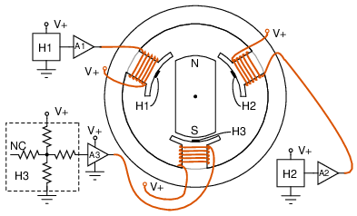
Who is online
Users browsing this forum: No registered users and 15 guests