
I should have said dv/dt , or delta voltage / delta time. Delta meaning in this case 'change of'. In this application, it's the ability of the optoisolator to give the correct output whilst the voltage difference between the input and output are changing. This is probably not a problem between cells, but between the pack as a whole and the master unit, can cause data loss or corruption.
Another concern is that of accuracy and resolution. 30mV resolution might be sufficient, but how accurate is that reading? If the units vary between each other by just plus or minus one 30mV step of resolution, that's nearly 0.1V which is starting to be a significant amount with these cells. The variation may well be more, although you can overcome that by calibrating each unit, storing a correction factor in memory. Generally a 10:1 ratio between accuracy and resolution is used. Don't assume you can select tighter tollerance components from a batch, the manufacturer may already have done so, leaving you with a dip in the middle of the standard distribution 'bell' curve.
As for filtering, you're going to need both analogue and digital filtering. A big problem with digital sampling systems is that of aliasing. Imagine you have a 100Hz square wave of 1V peak to peak. If you sampled it at 10mS intervals (100Hz) then depending on where in the waveform phase you sampled, you could get a reading of either 1V or 0V, whereas the average voltage is 500mV. With a passive filter, you want to have a cutoff frequency considerably less than the PWM frequency, but high enough not to give a sluggish response. With digital filtering, you want to take samples at the fastest convenient rate and then average them, which will help to remove the noise inherant to the A2D converter and reference voltage. You could simply take ten readings and then average them, or you might want a more sophisticated scheme, with a rolling average of the last ten samples and even a system that discards new samples that are too far different from the previous sample.
Old BMS General Thread
Moderators: GregsGarage, retepsnikrep
-
retepsnikrep

- Posts: 1387
- Joined: Sat May 26, 2007 4:50 pm
- Location: North Yorkshire England
- Contact:
I agree with Paul on most of that, Digital oversampling is pretty easy to implement and on the Slave todo list  along with a load of other stuff.
Ultimate accuracy will have to be tested and this is only MK1 Some compensation can be built in, i'm not going to get too worried by any errors less than +/-50mv.
I understand my 50 x 40ah cells have now left China on that slow boat, hopefully here in August.
Ultimate accuracy will have to be tested and this is only MK1
I understand my 50 x 40ah cells have now left China on that slow boat, hopefully here in August.
Regards Peter
Two MK1 Honda Insight's. One running 20ah A123 Lithium pack. One 8ah BetterBattery Nimh pack.
One HCH1 Civic Hybrid running 60ah A123 Lithium pack.
Two MK1 Honda Insight's. One running 20ah A123 Lithium pack. One 8ah BetterBattery Nimh pack.
One HCH1 Civic Hybrid running 60ah A123 Lithium pack.
-
retepsnikrep
- Posts: 1387
- Joined: Sat May 26, 2007 4:50 pm
- Location: North Yorkshire England
- Contact:
Phew! SOC calculation working
Hardware is done for MK1 Slave, the PCB files should be flying through the ether to a man in shed in China early next week for 100 boards to be made
Still working on Master PCB layout, might finish that next week and will order 5 I think as it's cheap enough.
Master Software is improving, and I now have the SOC calculation routine up and running.
If you have the Picaxe Basic Interpreter loaded on your Windows based PC then you can download a simulation version of it here and run that to see how it works.
www.rev-ed.co.uk/software/bas805.exe
www.solarvan.co.uk/bms/Soctest180708.txt
The Master Software is currently upto 500 bytes used out of a possible 4096 bytes available, only used 1/8th of available space so far Lot's of room for optimisation anyway i'm sure.
The SOC routine has been a tough one and at this stage it takes no account of variations in cell/battery chemistry and assumes a perfect cell. You get out what you put in There is no Temp/Peukert compensation or anything fancy like that at the moment. To be fair Lithium cells are quite good anyway and you get out what you put in near enough.
The routine catches charge/discharge data each second over a 1 minute period, and calculates an average 1 minute value for both. It then works out how much has been used or added in that 1 minute and then adds/subtracts that from the cell capacity/soc.
I'll add a 10% cutoff as well, so for my cells 40ah cells discharge will be limited to 36ah max. This will also help with errors in the SOC calculations which are again limited by the integer only maths.
After a mains external full charging cycle the SOC will be reset back to 100% or 40ah. The SOC counting will still take place during external charging and it will be interesting to watch the corelation between the amps counted in and out and the charging voltage cut off system.
Latest Software
www.solarvan.co.uk/bms/Master180708.txt
www.solarvan.co.uk/bms/Slave180708.txt
Limitations
Now I am working hard to make this as widely compatible with as many cells/batteries as possible, but I have had to keep an eye on my own specific requirements. To this end the new max cell capacity of the Master software is 65ah, this means I can use the full range of the limited 16 bit integer maths to maintain accuracy. It can be adjusted to allow upto 650ah capacity cells but at the expense of a decrease in SOC calculating accuracy. Also the maximum average current charge/discharge for any 1 minute period is limited to 65A to help with calculations. My Honda Insight falls within this range but again it can be adjusted to cover 650A at the expense of accuracy.
I don't know yet how accurate the whole thing will be, so I am erring on the side of maximum accuracy for my own application at present.
I'm trying to thoroughly document the software so you can adjust it for your own uses. I would welcome comments on the SOC routine and ideas to streamline/improve it please!!
Still working on Master PCB layout, might finish that next week and will order 5 I think as it's cheap enough.
Master Software is improving, and I now have the SOC calculation routine up and running.
If you have the Picaxe Basic Interpreter loaded on your Windows based PC then you can download a simulation version of it here and run that to see how it works.
www.rev-ed.co.uk/software/bas805.exe
www.solarvan.co.uk/bms/Soctest180708.txt
The Master Software is currently upto 500 bytes used out of a possible 4096 bytes available, only used 1/8th of available space so far
The SOC routine has been a tough one
The routine catches charge/discharge data each second over a 1 minute period, and calculates an average 1 minute value for both. It then works out how much has been used or added in that 1 minute and then adds/subtracts that from the cell capacity/soc.
I'll add a 10% cutoff as well, so for my cells 40ah cells discharge will be limited to 36ah max. This will also help with errors in the SOC calculations which are again limited by the integer only maths.
After a mains external full charging cycle the SOC will be reset back to 100% or 40ah. The SOC counting will still take place during external charging and it will be interesting to watch the corelation between the amps counted in and out and the charging voltage cut off system.
Latest Software
www.solarvan.co.uk/bms/Master180708.txt
www.solarvan.co.uk/bms/Slave180708.txt
Limitations
Now I am working hard to make this as widely compatible with as many cells/batteries as possible, but I have had to keep an eye on my own specific requirements. To this end the new max cell capacity of the Master software is 65ah, this means I can use the full range of the limited 16 bit integer maths to maintain accuracy. It can be adjusted to allow upto 650ah capacity cells but at the expense of a decrease in SOC calculating accuracy. Also the maximum average current charge/discharge for any 1 minute period is limited to 65A to help with calculations. My Honda Insight falls within this range but again it can be adjusted to cover 650A at the expense of accuracy.
I don't know yet how accurate the whole thing will be, so I am erring on the side of maximum accuracy for my own application at present.
I'm trying to thoroughly document the software so you can adjust it for your own uses. I would welcome comments on the SOC routine and ideas to streamline/improve it please!!
Regards Peter
Two MK1 Honda Insight's. One running 20ah A123 Lithium pack. One 8ah BetterBattery Nimh pack.
One HCH1 Civic Hybrid running 60ah A123 Lithium pack.
Two MK1 Honda Insight's. One running 20ah A123 Lithium pack. One 8ah BetterBattery Nimh pack.
One HCH1 Civic Hybrid running 60ah A123 Lithium pack.
-
Fufunka
- Posts: 28
- Joined: Mon Jul 30, 2007 9:59 pm
- Location: UnobtaniumVille, ThirdRockSolarSystem
- Contact:
Hi Peter, thanks for your hard work on this new version of BMS. I've been
following your efforts closely since that last published project on Solarvan
website, we exchanged a few emails then..
Please allow for just a few silly questions and ideas:
- what are the implication/constraints for using your BMS design in 336V
or even 576V system, i.e. 105/180 batt. cells (lithium) = slave modules?
- is the architecture able to handle it with some decent resolution, or would
it be possible/more desirable to brake it down to say several <40-60V
master blocks, which will then supply info to the single "Master Master"
board?
- do you plan to add into your "SOC meter" additional parameters like
regen, cumulative/instantenous economy (Wh/mi or Wh/km), inputs from
ext. sensors (rpm, vehicle speed, batt. temp, heating on/off, etc.), cell statistics on second tab/page, ..?
- your old mk1 bms had a great visual info output, I gather it will possible
to drive a similar bigger lcd panel in the future with some PICAXE
compatible board? http://www.solarvan.co.uk/bms.htm
For inspiration you might look at eBOX from ACP, you can
watch/download also narrated video about what is their "neard screen"
able to monitor ("eBOX first peak" link from the top) and the other picture galleries: http://www.stefanoparis.com/piaev/acpro ... index.html
-
retepsnikrep
- Posts: 1387
- Joined: Sat May 26, 2007 4:50 pm
- Location: North Yorkshire England
- Contact:
Fufunka wrote:what are the implication/constraints for using your BMS design in 336V or even 576V system, i.e. 105/180 batt. cells (lithium) = slave modules?
The Slaves have been designed to be used in large numbers, the board layout has taken into account the isolation required at high voltages and they should be good for use on upto 650v systems. The key factor is whether 180 slave optos paralleled onto a single bus causes a problem, If we use low leakage devices and make sure they are hard off when not transmitting but driven hard on/off when they are then the very high numbers of slaves in such a system may not cause a problem. The Cell V resolution is the same on a 65v or 650v system. The pack voltage is obtained by adding all the individual cell voltages together.
is the architecture able to handle it with some decent resolution, or would it be possible/more desirable to brake it down to say several <40-60V master blocks, which will then supply info to the single "Master Master" board?
I don't like the idea of sub master boards personally. The Master using the 28X1 Picaxe is limited to 128 cells due to limit of avaiable ram. The 40x1 Picaxe has double the ram so could cope with 256 cells.
As the number of cells grows the transmission of the cell data to the Master and other routines within it take proportionally longer to complete.
The Master pics in my prototype will be running at the lowest speed 4mhz, they can be clocked at upto 20mhz so hopefully would cope with the larger number of cells. The slaves can also be clocked at double speed (8mhz) which would double data bus transmission speed.
- do you plan to add into your "SOC meter" additional parameters like regen, cumulative/instantenous economy (Wh/mi or Wh/km), inputs from ext. sensors (rpm, vehicle speed, batt. temp, heating on/off, etc.), cell statistics on second tab/page, ..?
The soc routine already does "regen" as it is measures all current in/out of battery and uses that to calculate soc, the master already measures pack temp. I have not included speed/rpm etc in this version so far but spare input pins do exist on the pic so it should be possible.
- your old mk1 bms had a great visual info output, I gather it will possible to drive a similar bigger lcd panel in the future with some PICAXE
compatible board? http://www.solarvan.co.uk/bms.htm
I like the idea of one of these (Ebay 130235495669) in dash din lcd vga displays but I've no thought's at the moment on how to interface it to the Picaxe.
I have got a bigger Picaxe graphics lcd panel which I will fiddle with once it's all up and running.
The 20x2 text lcd I can scroll to provide extended information at touch of a button, but got to write all the master code for that
The amount of information available is only limited by the ingenuity/ability of the programmer. If others want to help add code they are willing to share, then see how the Master works at present and feel free to add something. To be completely honest
I'm not infalible
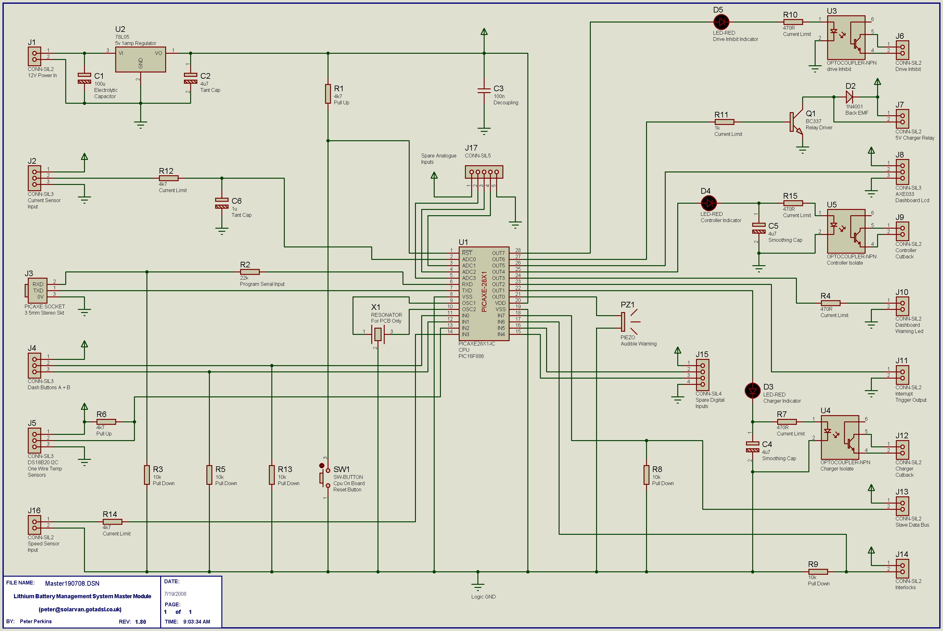
Here is the adjusted Master schematic with added Speed Sensor Input and other spare inputs made available
www.solarvan.co.uk/bms/Master190708.jpg
Regards Peter
Two MK1 Honda Insight's. One running 20ah A123 Lithium pack. One 8ah BetterBattery Nimh pack.
One HCH1 Civic Hybrid running 60ah A123 Lithium pack.
Two MK1 Honda Insight's. One running 20ah A123 Lithium pack. One 8ah BetterBattery Nimh pack.
One HCH1 Civic Hybrid running 60ah A123 Lithium pack.
-
retepsnikrep
- Posts: 1387
- Joined: Sat May 26, 2007 4:50 pm
- Location: North Yorkshire England
- Contact:
Slave update
Interrupts and Oversampling 
Re-written the slave code to remove the "Interrupt" command. Why you ask, well I was getting the odd result from time to time, and I realised by actually using an "Interrupt" it was doing exactly what it said on the tin Interrupting the program and jumping out of the data collection loop at all sorts of strange points, inc half way through calculations  and then sending the erroneous data to the Master
So I now have a pseudo interrupt, and just test what was the interrupt input pin when I have the correct data ready to be sent. If the Master is not calling for data then the Slave just continues in the normal loop.
I've also implemented 10x Oversampling, and the Slaves now calculate an average Cell Voltage from last 10 readings. Should be more accurate and help to smooth out the odd error.
Tidied up the Slave code as well, about 80 bytes used out of 256 available.
http://www.solarvan.co.uk/bms/Slave210708.txt
No further changes to Slave or Master Schematic/PCB since last update.
Master code still coming along, but I need to get a real Master built now to start bench testing the software, and iron out early errors before it get's too complicated.
Re-written the slave code to remove the "Interrupt" command. Why you ask, well I was getting the odd result from time to time, and I realised by actually using an "Interrupt" it was doing exactly what it said on the tin
So I now have a pseudo interrupt, and just test what was the interrupt input pin when I have the correct data ready to be sent. If the Master is not calling for data then the Slave just continues in the normal loop.
I've also implemented 10x Oversampling, and the Slaves now calculate an average Cell Voltage from last 10 readings. Should be more accurate and help to smooth out the odd error.
Tidied up the Slave code as well, about 80 bytes used out of 256 available.
http://www.solarvan.co.uk/bms/Slave210708.txt
No further changes to Slave or Master Schematic/PCB since last update.
Master code still coming along, but I need to get a real Master built now to start bench testing the software, and iron out early errors before it get's too complicated.
Regards Peter
Two MK1 Honda Insight's. One running 20ah A123 Lithium pack. One 8ah BetterBattery Nimh pack.
One HCH1 Civic Hybrid running 60ah A123 Lithium pack.
Two MK1 Honda Insight's. One running 20ah A123 Lithium pack. One 8ah BetterBattery Nimh pack.
One HCH1 Civic Hybrid running 60ah A123 Lithium pack.
-
retepsnikrep
- Posts: 1387
- Joined: Sat May 26, 2007 4:50 pm
- Location: North Yorkshire England
- Contact:
Video Interfacing and in car data displays
Video interfacing and in car displays!
I've been thinking about this, and really like the idea of this superbly simple single chip 8 pin dip solution for a video lcd display.
http://www.speechchips.com/shop/item.aspx?itemid=5
A lot of vehicles now have lcd monitors built into the dash and this could/should drive them if they have a compatible RCA 1v 75ohm Video input. You can also get one of these nice motorised in dash lcd things!
This looks like a gem and has a video input to display the bms data
E-Bay Item number: 130239538523
Yes the display chip has limited capabilities, but seems a bargain price to me and simple to add to the master pcb (which I will do this week) You don't have to install it on the pcb and can still use the two line lcd text module.
The chip accepts serial data from the master and generates RS170 (US NTSC Compatable) and CCIR (EU PAL Compatible) monochrome video that can be fed into any display/tv/monitor capable of displaying standard RCA Video.
Ohh err

Might even be able to add some graphics/bargraphs to it by modifying fonts etc
http://www.speechchips.com/downloads/sv2000.doc
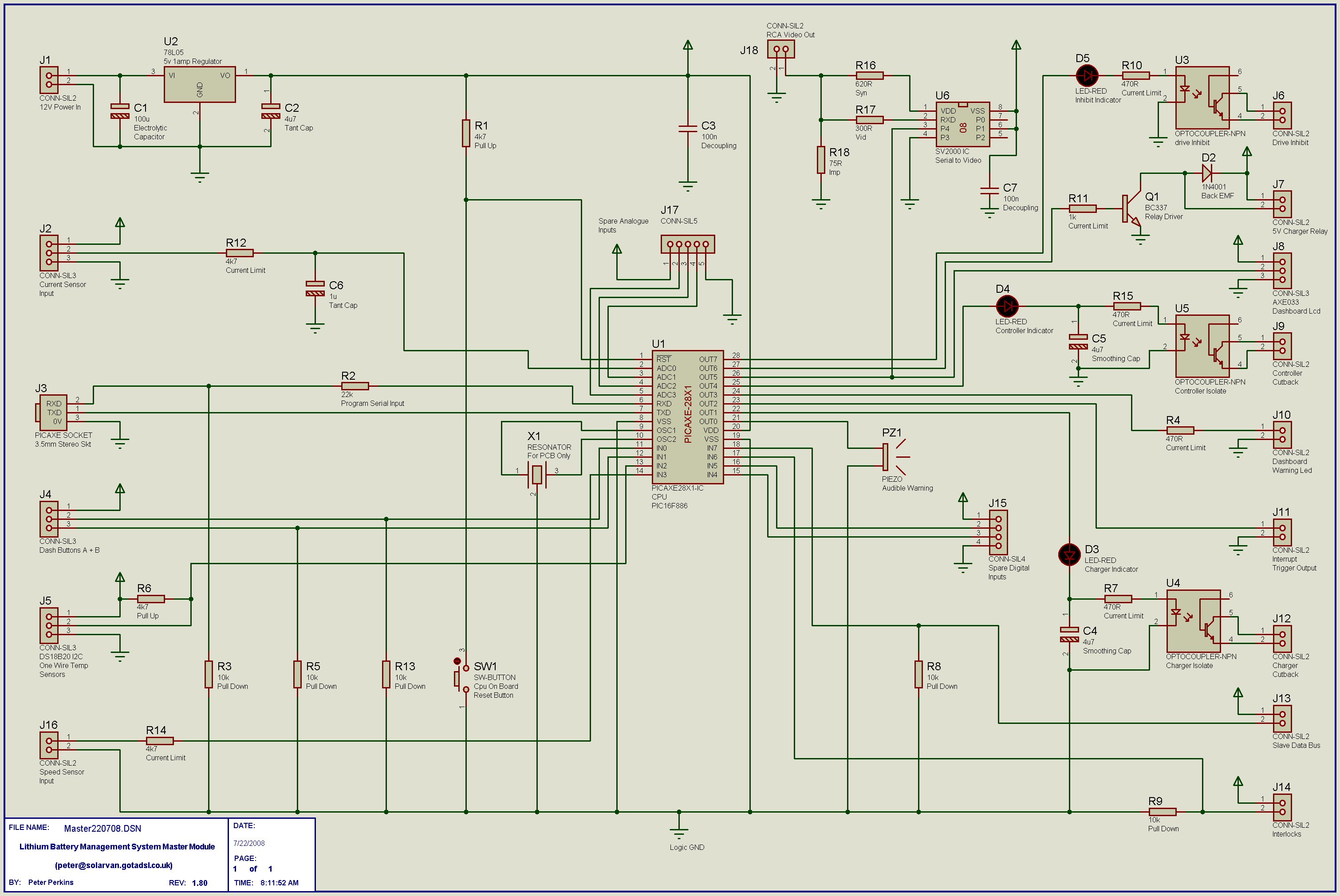
New Master Schematic incorporating Video output chip.
http://www.solarvan.co.uk/bms/Master220708.jpg
Latest Master Software incorporating Video output option
http://www.solarvan.co.uk/bms/Master220708.txt
I've been thinking about this, and really like the idea of this superbly simple single chip 8 pin dip solution for a video lcd display.
http://www.speechchips.com/shop/item.aspx?itemid=5
A lot of vehicles now have lcd monitors built into the dash and this could/should drive them if they have a compatible RCA 1v 75ohm Video input. You can also get one of these nice motorised in dash lcd things!
This looks like a gem and has a video input to display the bms data
E-Bay Item number: 130239538523
Yes the display chip has limited capabilities, but seems a bargain price to me and simple to add to the master pcb (which I will do this week) You don't have to install it on the pcb and can still use the two line lcd text module.
The chip accepts serial data from the master and generates RS170 (US NTSC Compatable) and CCIR (EU PAL Compatible) monochrome video that can be fed into any display/tv/monitor capable of displaying standard RCA Video.
Ohh err
Might even be able to add some graphics/bargraphs to it by modifying fonts etc
http://www.speechchips.com/downloads/sv2000.doc
New Master Schematic incorporating Video output chip.
http://www.solarvan.co.uk/bms/Master220708.jpg
Latest Master Software incorporating Video output option
http://www.solarvan.co.uk/bms/Master220708.txt
Last edited by retepsnikrep on Wed Jul 23, 2008 3:05 pm, edited 1 time in total.
Regards Peter
Two MK1 Honda Insight's. One running 20ah A123 Lithium pack. One 8ah BetterBattery Nimh pack.
One HCH1 Civic Hybrid running 60ah A123 Lithium pack.
Two MK1 Honda Insight's. One running 20ah A123 Lithium pack. One 8ah BetterBattery Nimh pack.
One HCH1 Civic Hybrid running 60ah A123 Lithium pack.
-
retepsnikrep
- Posts: 1387
- Joined: Sat May 26, 2007 4:50 pm
- Location: North Yorkshire England
- Contact:
Getting There
Another 10hrs on Master Software today, it's coming along
Added
1) Extended BMS Parameters Display inc Individual Cell V etc
2) EEPROM Storage routines to save Soc/Odometer/WhMile readings when Master unit off
3) Charging routine
4) Speedo Input
5) Interlocks
Lots of bugfixes and tweaks to the way variables were used
To do List
1) WhMile/Distance/Speed calculations
2) Warning Messages and actions
Loads of other stuff I have forgotten
And the inevitable Debugging
990 bytes used so far out of 4096 available
http://www.solarvan.co.uk/bms/Master230708v66.txt
Sorry about the formatting of the code, it is correct in the Program editor but when converted to plain text it goes wibble Wish I knew why!
Added
1) Extended BMS Parameters Display inc Individual Cell V etc
2) EEPROM Storage routines to save Soc/Odometer/WhMile readings when Master unit off
3) Charging routine
4) Speedo Input
5) Interlocks
Lots of bugfixes
To do List
1) WhMile/Distance/Speed calculations
2) Warning Messages and actions
Loads of other stuff I have forgotten
And the inevitable Debugging
990 bytes used so far out of 4096 available
http://www.solarvan.co.uk/bms/Master230708v66.txt
Sorry about the formatting of the code, it is correct in the Program editor but when converted to plain text it goes wibble
Last edited by retepsnikrep on Wed Jul 23, 2008 6:39 pm, edited 1 time in total.
Regards Peter
Two MK1 Honda Insight's. One running 20ah A123 Lithium pack. One 8ah BetterBattery Nimh pack.
One HCH1 Civic Hybrid running 60ah A123 Lithium pack.
Two MK1 Honda Insight's. One running 20ah A123 Lithium pack. One 8ah BetterBattery Nimh pack.
One HCH1 Civic Hybrid running 60ah A123 Lithium pack.
-
retepsnikrep
- Posts: 1387
- Joined: Sat May 26, 2007 4:50 pm
- Location: North Yorkshire England
- Contact:
My Brains Gone!
Speed of vehicle is measured by VSS (Vehicle speed sensor) which gives 4550 pulses per mile travelled.
One mile = 5280 feet.
I am counting the number of pulses from the sensor each second.
So pulses per second = X
OK
So can someone help this old idiot with the formula to calculate speed mph and distance travelled from the above info.
Remember no decimals allowed everything has to be scaled to fit into 16bit word integer maths (0-65235)
Thanks
Regards Peter
Two MK1 Honda Insight's. One running 20ah A123 Lithium pack. One 8ah BetterBattery Nimh pack.
One HCH1 Civic Hybrid running 60ah A123 Lithium pack.
Two MK1 Honda Insight's. One running 20ah A123 Lithium pack. One 8ah BetterBattery Nimh pack.
One HCH1 Civic Hybrid running 60ah A123 Lithium pack.
Peter I will have a go for you.
we know that there are 4550 pulses per mile traveled and
you are reading the pulses per second
s = speed in MPH
x = pulses per second
s = (x*3600)/4550
Should give pulses per hour divided by pulses per mile to give you a mile per hour figure.
so for a 60mph reading you would be reading about 76 pulses per second.
Let me know what you think.
Who is online
Users browsing this forum: No registered users and 21 guests