How is everyone getting on with building/installing the new boards?
Any pics of your installs / test setups yet?
Old BMS Hardware Thread
Moderators: GregsGarage, retepsnikrep
-
retepsnikrep

- Posts: 1387
- Joined: Sat May 26, 2007 4:50 pm
- Location: North Yorkshire England
- Contact:
Re: BMS Hardware
Regards Peter
Two MK1 Honda Insight's. One running 20ah A123 Lithium pack. One 8ah BetterBattery Nimh pack.
One HCH1 Civic Hybrid running 60ah A123 Lithium pack.
Two MK1 Honda Insight's. One running 20ah A123 Lithium pack. One 8ah BetterBattery Nimh pack.
One HCH1 Civic Hybrid running 60ah A123 Lithium pack.
-
retepsnikrep
- Posts: 1387
- Joined: Sat May 26, 2007 4:50 pm
- Location: North Yorkshire England
- Contact:
Re: BMS Hardware
Here is a new schematic for a single slave. Comments?
http://www.solarvan.co.uk/bms/DigitalSlave210210.jpg
Reduced component count. 1/2 the number of resistors and only one capacitor!
Slave load monitoring. Detect load open circuit or load stuck on etc.
PWM Load Control. Any load current available upto 350ma with 10R resistor.
Possible ULPWU Sleep and wake up function?
I am hoping to use the PIC internal weak pull up resistor function to get rid of two external resistors on GP0 & GP1
Note no ICSP, it's impossible to implement with the new functions and not required IMHO.
Regards Peter
Two MK1 Honda Insight's. One running 20ah A123 Lithium pack. One 8ah BetterBattery Nimh pack.
One HCH1 Civic Hybrid running 60ah A123 Lithium pack.
Two MK1 Honda Insight's. One running 20ah A123 Lithium pack. One 8ah BetterBattery Nimh pack.
One HCH1 Civic Hybrid running 60ah A123 Lithium pack.
-
GregsGarage
- Posts: 870
- Joined: Tue Apr 01, 2008 5:27 pm
- Location: Galashiels, Scottish Borders
- Contact:
Re: BMS Hardware
retepsnikrep wrote:Here is a new schematic for a single slave. Comments?
http://www.solarvan.co.uk/bms/DigitalSlave210210.jpg
Looks good. You don't show pin 1 of the pic. I assume it is connected to cell positive. Maybe move R1 to J4, pin 1 that way if you have a short on the slave bus you don't have full cell voltage, it would be limited by R1.
I have been reading up a bit on surface mount components. People have been using modified toaster ovens as reflow ovens for surface mount components. Is it worth considering for the next pcb?
http://en.wikipedia.org/wiki/User:WillWare/Homebrew_surface-mount_construction
Maybe do what we can with surface mount and then solder on the through hole parts after?
Greg Fordyce
Daewoo Matiz
http://www.evalbum.com/4191
Daewoo Matiz
http://www.evalbum.com/4191
-
retepsnikrep
- Posts: 1387
- Joined: Sat May 26, 2007 4:50 pm
- Location: North Yorkshire England
- Contact:
Re: BMS Hardware
Pin 1 and 8 are not shown as the schematic program automatically connects them to + & - supply.
They appear on the generated netlist.
I'm not sure about SM, I've never tried it.
After 45 years of soldering i'm good at normal soldering and board building so have confidence in the things I have made. Anyone can make up our current boards with a modicum of soldering ability.
If we go to SM then we should investigate getting the boards assembled IMO. We will still need a 8 pin dil socket and standard pic for the slave chip as it has to be removed to be programmed in the programmer.
Regards Peter
Two MK1 Honda Insight's. One running 20ah A123 Lithium pack. One 8ah BetterBattery Nimh pack.
One HCH1 Civic Hybrid running 60ah A123 Lithium pack.
Two MK1 Honda Insight's. One running 20ah A123 Lithium pack. One 8ah BetterBattery Nimh pack.
One HCH1 Civic Hybrid running 60ah A123 Lithium pack.
-
GregsGarage
- Posts: 870
- Joined: Tue Apr 01, 2008 5:27 pm
- Location: Galashiels, Scottish Borders
- Contact:
Re: BMS Hardware
O.K. Could be confusing for someone trying to build the circuit from the schematic, might be better to draw them in.retepsnikrep wrote:Pin 1 and 8 are not shown as the schematic program automatically connects them to + & - supply.
They appear on the generated netlist.
How about moving R1? Put it next to R3 on the schematic. I am thinking possible wiring problems between slave boards. Put the current limit resistor as close to the voltage source as possible that way any shorts cause fewer problems.
Point taken on the surface mount idea. I just found it interesting that it is possible to manufacture them in your garden shed. I suppose it would still require a need for quite a few boards before it becomes practical.
Greg Fordyce
Daewoo Matiz
http://www.evalbum.com/4191
Daewoo Matiz
http://www.evalbum.com/4191
-
retepsnikrep
- Posts: 1387
- Joined: Sat May 26, 2007 4:50 pm
- Location: North Yorkshire England
- Contact:
Re: BMS Hardware
Good Idea i'll move R1
Can't show pin 1 and 8 they don't (visibly) exist on the Pic12f683 model in my schematic program.
Have to add a note somewhere on diagram.
If we get Mike to tweak the layout and reduce isolation a bit, now we have half the resistors and one less cap might be able to get 25 per board which would be my design target. I need two boards for 50 cells. Interference is not a problem, if it works in the Insight which it does without issue I'm confident it will work anywhere!
Thinking about the current layout if you run into problems with the 350ma load resistors and voltage drops we could turn them off for 50% of the time in the slave software making the load an average of 175ma or 75% off giving 87.5ma
I'll elaborate a bit more on this later on software thread.
Regards Peter
Two MK1 Honda Insight's. One running 20ah A123 Lithium pack. One 8ah BetterBattery Nimh pack.
One HCH1 Civic Hybrid running 60ah A123 Lithium pack.
Two MK1 Honda Insight's. One running 20ah A123 Lithium pack. One 8ah BetterBattery Nimh pack.
One HCH1 Civic Hybrid running 60ah A123 Lithium pack.
-
martinwinlow
- Posts: 79
- Joined: Mon Jun 11, 2007 9:35 am
- Location: Herts, UK
Re: BMS Hardware
Peter - Is there a component list for the master and digital slave boards somewhere? I have gone through all 3 threads and have not found one yet...
Regards, Martin.
Regards, Martin.
Regards, Martin Winlow
Herts, UK
http://www.evalbum.com/2092
www.winlow.co.uk
Herts, UK
http://www.evalbum.com/2092
www.winlow.co.uk
-
martinwinlow
- Posts: 79
- Joined: Mon Jun 11, 2007 9:35 am
- Location: Herts, UK
Re: BMS Hardware
Peter,
A few more Qs...
The 16 x slave boards... I assume the components and circuit for each of the 16 'sub-PCBs' are the same as the single slave circuit in the DigitalSlave041208.jpg in the currant BMSProject041208.zip file? Or is there a different diagram somewhere?
What are the beige resistor-like components you sent me marked 'CRU1A' and 'CQ1AF1'?
There is a thread titled 'DC-DC rating and usage' on the EVDL at the moment and in one of the latest posts there is talk of a simple method of switching off the charger if the pack volts rise too high - I guess a last ditch safety cutoff. Lee Hart suggested a 24V relay in series with a number of suitably rated zener diodes across the pack that pulls in at the required max pack voltage cutting off the charger. I'd like to do the same and wonder if there is anything I'd have to look out for when using it with the BMS?
Regards, Martin.
Regards, Martin Winlow
Herts, UK
http://www.evalbum.com/2092
www.winlow.co.uk
Herts, UK
http://www.evalbum.com/2092
www.winlow.co.uk
-
retepsnikrep
- Posts: 1387
- Joined: Sat May 26, 2007 4:50 pm
- Location: North Yorkshire England
- Contact:
Re: BMS Hardware
Martin
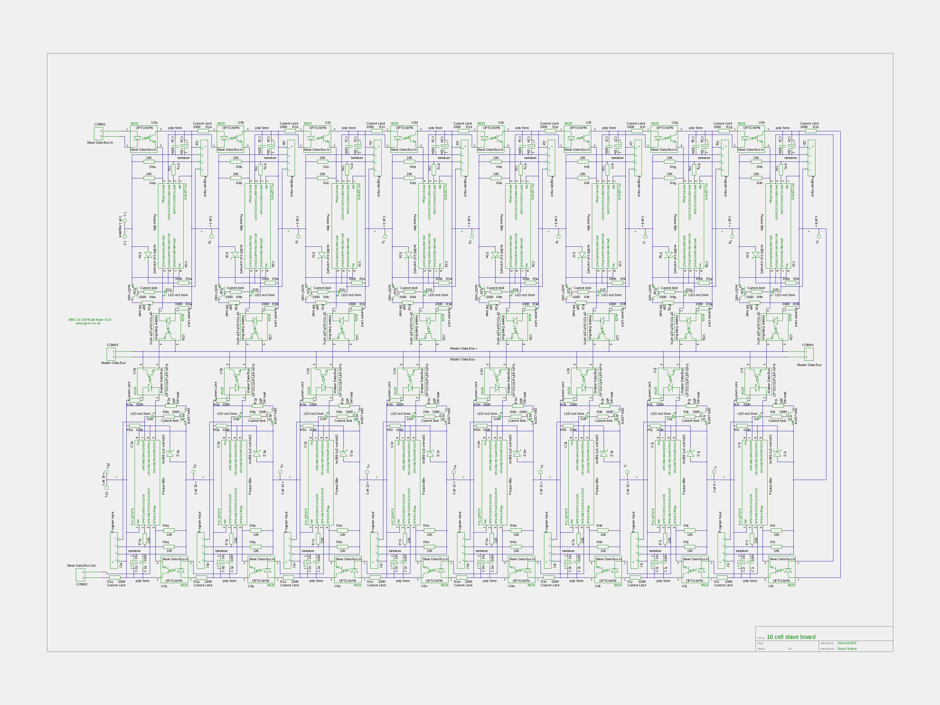
This is the schematic for the 16 cell slave it shows the components values.
http://www.solarvan.co.uk/bms/16cell311009.jpeg
If you zoom in to cell one at the top left.
You can omit R6 & R7 if you are not using picaxe slaves.
I used a 22k resistor for R5 and a 4k7 for R4 but anything between 1-10k is probably fine.
Ditto for rest of board. I think greg did a component list?
Have you measured the value of the odd component i sent you? I can't say what it is without seeing a pic of it.
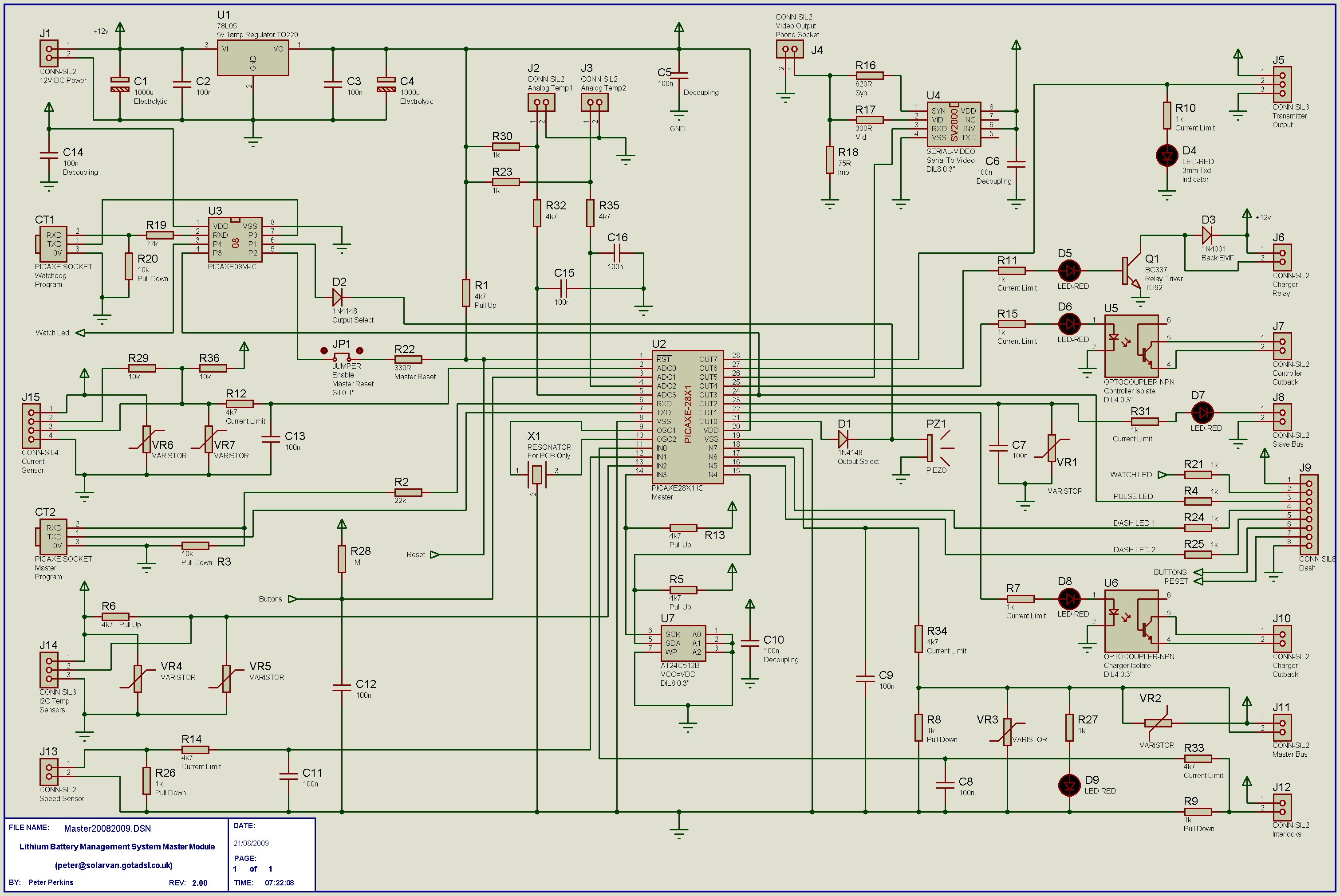
This is the master V2 schematic there is no component list yet AFAIK you have to work from the schematic.
http://www.solarvan.co.uk/bms/Master20082009.jpg
Don't include C9, C7 or C11. You can also omit R18.
Re you final safety zener cut off. I would use it to kill the supply to the BMS, if the BMS is off so is the main charger relay. Anyway howevere you include it the BMS won't mind.
This is the schematic for the 16 cell slave it shows the components values.
http://www.solarvan.co.uk/bms/16cell311009.jpeg
If you zoom in to cell one at the top left.
You can omit R6 & R7 if you are not using picaxe slaves.
I used a 22k resistor for R5 and a 4k7 for R4 but anything between 1-10k is probably fine.
Ditto for rest of board. I think greg did a component list?
Have you measured the value of the odd component i sent you? I can't say what it is without seeing a pic of it.
This is the master V2 schematic there is no component list yet AFAIK you have to work from the schematic.
http://www.solarvan.co.uk/bms/Master20082009.jpg
Don't include C9, C7 or C11. You can also omit R18.
Re you final safety zener cut off. I would use it to kill the supply to the BMS, if the BMS is off so is the main charger relay. Anyway howevere you include it the BMS won't mind.
Regards Peter
Two MK1 Honda Insight's. One running 20ah A123 Lithium pack. One 8ah BetterBattery Nimh pack.
One HCH1 Civic Hybrid running 60ah A123 Lithium pack.
Two MK1 Honda Insight's. One running 20ah A123 Lithium pack. One 8ah BetterBattery Nimh pack.
One HCH1 Civic Hybrid running 60ah A123 Lithium pack.
-
retepsnikrep
- Posts: 1387
- Joined: Sat May 26, 2007 4:50 pm
- Location: North Yorkshire England
- Contact:
Re: BMS Hardware
Here is a parts list spreadsheet created by Rick.
I'll share it via google and anyione can edit it.
It doesnt include the 16 cell slave boards or the single slave boards yet. So if someone wants to add them please do.
I suggest we follow Ricks layout and add some columns for UK parts as required.
https://spreadsheets.google.com/ccc?key ... yeHc&hl=en
Thanks to Rick for starting us off.
Regards Peter
Two MK1 Honda Insight's. One running 20ah A123 Lithium pack. One 8ah BetterBattery Nimh pack.
One HCH1 Civic Hybrid running 60ah A123 Lithium pack.
Two MK1 Honda Insight's. One running 20ah A123 Lithium pack. One 8ah BetterBattery Nimh pack.
One HCH1 Civic Hybrid running 60ah A123 Lithium pack.
Who is online
Users browsing this forum: No registered users and 59 guests