A few years ago (while we were doing Robot Wars in fact) I designed a mechanical speed controller. We needed a controller at the time which would handle 1200A at 24v - and such a thing just did not exist.
As it turned out, I built an electronic one using big IGBT's - but another chap named Steve Davis built and used this.
I thought it might be useful to anyone wanting to build an EV on a non existent budget.
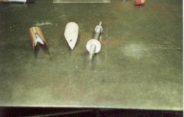
Take a cylinder of PTFE & cut a 'V' in one end (as shown on the left (the white bit) and then take a cylinder of Copper and cut such that the two fit neatly together. Drill an axial hole up the middle to mount the two components on a shaft. Glue the whole lot together.
Put the spindle in a drill chuck to turn and use emery cloth to polish the surface & remove any burrs.
Using the brush assembly from a DC motor (selected such that the brushes will handle the required current), mount two brushes diametrically opposite one another such that their mounting can slide along the length of the commutator (the Copper & PTFE bit), or arrange that the brushes remain stationary and the commutator slides. Connect a small, high speed motor such that the commutator assembly rotates on its axis.
As the brushes move along the length of the commutator, the proportion of the time they are in contact with the copper changes from 100% to 0% changing the power delivered to your drive motors in the same proportion (PWM)
Use an RC Servo to move the brushes with a spring return to the PTFE end such that it will fail safe, although I would recommend using a solenoid switch to engage & disengage the power to the whole system. Reversing is achieved with either a big relay or four solenoid switches acting as a change-over.
A System such as this can be made to handle HUGE currents and the cost and complexity are roughly the same regardless. I would use the brush set from an automotive starter motor (removing the two brushes that connect to ground and separating the contacts which are normally live). The main loss in such a system is the motor which drives the commutator assembly although this should be fairly free running and the losses low. It does not require any special tooling to build (I've built one with nothing more than a hack saw and a drill (although I started with copper & PTFE tube into which the axle fitted neatly. Glue the components together with an epoxy otherwise the glue may melt!
Mechanical Speed Controller
-
- Posts: 63
- Joined: Thu Apr 24, 2008 5:23 pm
- Location: Bath
Didn't seem to be too much of a problem because the duty cycle at that point is low - giving it time to cool down.
We decided to make the tip of the copper part about the same width as the contacts in the commutator - so I guess the current density will be about the same worst case.
Durability didn't seem to be too much of a problem - after all, it's not doing anything a commutator isn't!
The reason I was thinking about this again was that I may need a high (1000A @ 300v) current AC drive - and there is a fairly simple extension to this which will deliver just that - but at the moment I can only see how to make it work in a star wired configuration whereas my motor is delta wired.
Si
Great to see that this can work..
I've been thinking out this kind of device for a while but I hadn't thought of the V cylinder idea. I was looking at using an actual commutator and replacing the armature windings with sliprings so you could switch the comm segments in and out. This would only give a stepped control as you gradually switch in more segments.
On your design, Are you taking the power in one brush and out the other, or into the shaft and out of both brushes simultaneously?
I'd also considered using this kind of arrangement just to switch the gate current to a bank of mosfets. Another idea I had for low curent switching was a car distributer with a lever to adjust the dwell setting on the points so when it's all the way in the points stay open and when all the way out they stay closed. This should be able to handle about 4000 rpm with four switchings per rev, giving 16khz operating frequency. I have to say, I never got round to testing it though......
I've got a Curtis controller now.
Cheers.
I like the points idea - very simple and could be scaled up some.
If you were to use a set of contacts in a vacuum or arc suppressing oil that could be brought together magnetically you might be able to operate it using spinning magnets and changing the proximity of the contacts to the magnets to alter the dwell. This would give you something capable of switching quite high currents at high voltage.
Si
Are you able to supply video of this?
Fantastic, I love it, so simple.
I bet it is fairly quiet too?
Are you able to supply video of this in action, with a run through of the connections etc?
I bet it is fairly quiet too?
Are you able to supply video of this in action, with a run through of the connections etc?
- Night Train
- Posts: 350
- Joined: Sat Jun 21, 2008 11:55 pm
- Location: Manchester
Is there anymore information on this, Simon?
I think given my lack of budget to do anything (and minimal remaining knowledge on electronics) I will be keeping things mechanical.
I was figuring on the throttle pedal acting directly, via cable or rods, to move the brush mounting plate against the return springs so that the only electrical aspect would be the spinning motor. I was also thinking about using the movement of the brush mounting plate to switch the little motor on and off. Maybe a micro switch at the rest position to break the supply to the little motor but the moment the throttle is pressed the switch makes and sets the shaft spinning.
Also, if there is a significant heat generation then perhaps putting a fan impeller on the end of the shaft and then the whole thing in a housing would keep things under control.
I will make a working model to test it out.
Who is online
Users browsing this forum: No registered users and 19 guests