Old BMS Hardware Thread

Threads relating to the BMS system begun by Peter Perkins

Moderators: GregsGarage, retepsnikrep

martinwinlow
Posts: 79
Joined: Mon Jun 11, 2007 9:35 am
Location: Herts, UK

Re: Old BMS Hardware Thread

Postby martinwinlow » Fri Apr 01, 2011 3:16 pm

GregsGarage wrote: the biggest problem is that the paktrakr draws power from the pack in an uneven way


Hi Greg, This is exactly what I was referring to when I said "and also not being terribly suited to Li cells"...! It drives me round the twist... especially the drain that the last remote puts on the 3 cells that power it as it does the display too. MW
Regards, Martin Winlow
Herts, UK
http://www.evalbum.com/2092
www.winlow.co.uk

GregsGarage
Posts: 870
Joined: Tue Apr 01, 2008 5:27 pm
Location: Galashiels, Scottish Borders
Contact:

Re: Old BMS Hardware Thread

Postby GregsGarage » Fri Apr 01, 2011 4:35 pm

:D :D :D :D Peter, your opto isolator trick does the job! :D :D :D :D

I can now power the master from the same 12v supply as my controller. Scoping pin2 of J11 gives me the same scope pattern as my first one in the previous post with the controller running. Scoping the other side of the opto still shows all the noise I had in the second image, but the opto isn't passing that through. My guess is the spikes are to fast for the opto to respond, so it is acting as a sort of filter. The real test will be when I reconnect the front slave board and see how it behaves, that one is closest to the noise and removing it had reduced the interferance problem somewhat. Hopefully earthing the cable shielding will help.
Greg Fordyce

Daewoo Matiz
http://www.evalbum.com/4191

User avatar
retepsnikrep
Posts: 1387
Joined: Sat May 26, 2007 4:50 pm
Location: North Yorkshire England
Contact:

Re: Old BMS Hardware Thread

Postby retepsnikrep » Fri Apr 01, 2011 6:03 pm

GregsGarage wrote: My guess is the spikes are to fast for the opto to respond, so it is acting as a sort of filter.
Correct nice easy fix. Might incorporate it as an option on next master board with a small dc-dc and opto on board ;)

Plus the spikes are likely to be high voltage which upsets the pic, but miniscule current and not enough to drive the led either.
Regards Peter

Two MK1 Honda Insight's. One running 20ah A123 Lithium pack. One 8ah BetterBattery Nimh pack.
One HCH1 Civic Hybrid running 60ah A123 Lithium pack.

GregsGarage
Posts: 870
Joined: Tue Apr 01, 2008 5:27 pm
Location: Galashiels, Scottish Borders
Contact:

Re: Old BMS Hardware Thread

Postby GregsGarage » Fri Apr 01, 2011 6:53 pm

retepsnikrep wrote:Might incorporate it as an option on next master board with a small dc-dc and opto on board ;)


To me it looks like it should be standard issue. :wink:
Greg Fordyce

Daewoo Matiz
http://www.evalbum.com/4191

User avatar
retepsnikrep
Posts: 1387
Joined: Sat May 26, 2007 4:50 pm
Location: North Yorkshire England
Contact:

Re: Old BMS Hardware Thread

Postby retepsnikrep » Sat Apr 02, 2011 3:18 am

A redesign of how the bus operates would be better i think. Current Loops anyone.

http://www.bapihvac.com/CatalogPDFs/I_A ... _Loops.pdf

But yes, as a standby and easy fix it seems to work. You can adjust the resistor higher to reduce current load on your dc-dc or battery to the highest value which allows reliable operation. You may be able to reduce the current quite a bit. Try a 5-10k multiturn pot and fiddle about with it. That would be useful info as well. :wink:
Regards Peter

Two MK1 Honda Insight's. One running 20ah A123 Lithium pack. One 8ah BetterBattery Nimh pack.
One HCH1 Civic Hybrid running 60ah A123 Lithium pack.

GregsGarage
Posts: 870
Joined: Tue Apr 01, 2008 5:27 pm
Location: Galashiels, Scottish Borders
Contact:

Re: Old BMS Hardware Thread

Postby GregsGarage » Sat Apr 02, 2011 11:16 am

Wikipedia has an entry on current loops, http://en.wikipedia.org/wiki/Current_loop. Looks promising, the wiki entry discusses digital applications of current loops including opto isolation which we need. So it looks promising.

EDIT: This has also interested me for a while now. http://www.evdl.org/docs/evilbus.pdf
Greg Fordyce

Daewoo Matiz
http://www.evalbum.com/4191

GregsGarage
Posts: 870
Joined: Tue Apr 01, 2008 5:27 pm
Location: Galashiels, Scottish Borders
Contact:

Re: Old BMS Hardware Thread

Postby GregsGarage » Sat Apr 02, 2011 4:59 pm

GregsGarage wrote:...The real test will be when I reconnect the front slave board and see how it behaves, that one is closest to the noise and removing it had reduced the interference problem somewhat. Hopefully earthing the cable shielding will help.


Got the front slave board reconnected and took the car for a short test drive. No interference problems what so ever. :D The front slave was going to be the real test as it was worst affected due to being near the motor and controller. Considering that the master pcb is laying in the passenger footwell on top of a bunch of wires and that none of the shielding in my master and slave bus wires is earthed, I would say that is pretty impressive. :shock:
Greg Fordyce

Daewoo Matiz
http://www.evalbum.com/4191

GregsGarage
Posts: 870
Joined: Tue Apr 01, 2008 5:27 pm
Location: Galashiels, Scottish Borders
Contact:

Master bus current loop.

Postby GregsGarage » Sat Apr 02, 2011 10:24 pm

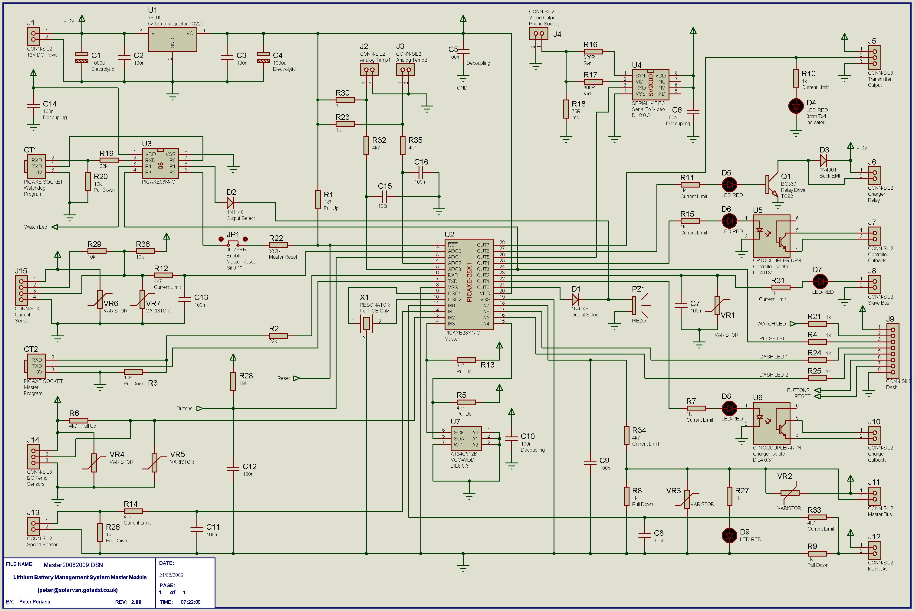
I have been looking at current loops, interesting history behind them. Here's how I think it could be implemented on Master V2. Looking at the schematic http://www.solarvan.co.uk/bms/Master20082009.jpg you would need to remove the 5 volt supply from J11 pin one (well don't actually remove the 5 volt feed from J11, just connect the wire to the current source) and instead feed it with a device like a LM134/LM234/LM334. Set this device as a 5ma current source. Then remove VR2, VR3, C9 (should already be removed), R27 and D9. Note, we leave R8 (1k) and replace R34 with a jumper/0 ohm link. Now what happens is the LMx34 will supply 5ma current whenever one of the slave master bus optos conducts and 5ma across a 1k resistor (R8) generates 5 volts that the pic will see as a pulse. Or you could set the LMx34 for 1ma and R8 to 5k, this also gives 5 volts. 8)

Nice thing about this is the slaves remain unchanged. 8) 8)

I won't have time to try this out anytime soon, but if anyone else wants to see if it will work, please let us know. :D
Greg Fordyce

Daewoo Matiz
http://www.evalbum.com/4191

User avatar
retepsnikrep
Posts: 1387
Joined: Sat May 26, 2007 4:50 pm
Location: North Yorkshire England
Contact:

Re: Old BMS Hardware Thread

Postby retepsnikrep » Sun Apr 03, 2011 3:42 pm

All good news Greg. Now get it all finished LOL!!!

I'm away in cornwall so watching from afar.
Regards Peter

Two MK1 Honda Insight's. One running 20ah A123 Lithium pack. One 8ah BetterBattery Nimh pack.
One HCH1 Civic Hybrid running 60ah A123 Lithium pack.

GregsGarage
Posts: 870
Joined: Tue Apr 01, 2008 5:27 pm
Location: Galashiels, Scottish Borders
Contact:

Re: Old BMS Hardware Thread

Postby GregsGarage » Sun Apr 03, 2011 9:28 pm

Rapid have a alternative to the LMx34 series devices, its here. It's a simple axial leaded device that is fixed at 5.6ma. I am ordering a couple to try.
Greg Fordyce

Daewoo Matiz
http://www.evalbum.com/4191


Return to “BMS thread”

Who is online

Users browsing this forum: No registered users and 19 guests